-
 Approved by ATEX, IECEx Group I MI Ex ia I Ma f Group II IGD Ex ia IIC T6 Ga Ex ia IIIC T850 C Da Zones 0, 1, 2, 20, 21 & 22 Conforms to: EN 60079-0:2012 + All:2013 (IEC 60079-0:2011) EN-60079-11:2012 + (IEC 60079-11:2011) Diode Polarised & End of line resistor compatible White base version available MOQ apply Dustproof & Weatherproof; C-Tec - LED Beacon - Datasheet C-Tec - Installation Guide
 -
 Zones 0, 1, 2, 20, 21 and 22 ATEX and IECEx approved IP66 rated Surface Mount Polycarbonate housing material; C-Tec - Electronic Sounder - Datasheet C-Tec - Installation Guide
 -
 Approved by ATEX, IECEx Group I MI Ex ia I Ma f Group II IGD Ex ia IIC T6 Ga Ex ia IIIC T850 C Da Zones 0, 1, 2, 20, 21 & 22 Conforms to: EN 60079-0:2012 + All:2013 (IEC 60079-0:2011) EN-60079-11:2012 + (IEC 60079-11:2011) Diode Polarised & End of line resistor compatible White base version available MOQ apply Dustproof & Weatherproof; C-Tec - LED Beacon - Datasheet C-Tec - Installation Guide
 -
 Approved by ATEX, IECEx Group I MI Ex ia I Ma f Group II IGD Ex ia IIC T6 Ga Ex ia IIIC T850 C Da Zones 0, 1, 2, 20, 21 & 22 Conforms to: EN 60079-0:2012 + All:2013 (IEC 60079-0:2011) EN-60079-11:2012 + (IEC 60079-11:2011) Diode Polarised & End of line resistor compatible White base version available MOQ apply Dustproof & Weatherproof; C-Tec - LED Beacon - Datasheet C-Tec - Technical Information C-Tec - Installation Guide
 -
 Approved by ATEX, IECEx Group I MI Ex ia I Ma Group II IGD Ex ia IIC T6 Ga Ex ia IIIC T850 C Da Zones 0, 1, 2, 20, 21 & 22 Conforms to: EN 60079-0:2012 + All:2013 (IEC 60079-0:2011) EN-60079-11:2012 + (IEC 60079-11:2011) Diode Polarised & End of line resistor compatible White base version available MOQ apply Dustproof & Weatherproof; C-Tec - LED Beacon - Datasheet C-Tec - Technical Information C-Tec - Installation Guide
 -
 Approved by ATEX, IECEx Group I MI Ex ia I Ma Group II IGD Ex ia IIC T6 Ga Ex ia IIIC T850 C Da Zones 0, 1, 2, 20, 21 & 22 Conforms to: EN 60079-0:2012 + All:2013 (IEC 60079-0:2011) EN-60079-11:2012 + (IEC 60079-11:2011) Diode Polarised & End of line resistor compatible White base version available MOQ apply Dustproof & Weatherproof; C-Tec - LED Beacon - Datasheet C-Tec - Technical Information C-Tec - Installation Guide
 -
 Approved by ATEX, IECEx Group I MI Ex ia I Ma f Group II IGD Ex ia IIC T6 Ga Ex ia IIIC T850 C Da Zones 0, 1, 2, 20, 21 & 22 Conforms to: EN 60079-0:2012 + All:2013 (IEC 60079-0:2011) EN-60079-11:2012 + (IEC 60079-11:2011) Diode Polarised & End of line resistor compatible White base version available MOQ apply Dustproof & Weatherproof; C-Tec - LED Beacon - Datasheet C-Tec - Technical Information C-Tec - Installation Guide
 -
 Approved by ATEX, IECEx Group I MI Ex ia I Ma Group II IGD Ex ia IIC T6 Ga Ex ia IIIC T850 C Da Zones 0, 1, 2, 20, 21 & 22 Conforms to: EN 60079-0:2012 + All:2013 (IEC 60079-0:2011) EN-60079-11:2012 + (IEC 60079-11:2011) Diode Polarised & End of line resistor compatible White base version available MOQ apply Dustproof & Weatherproof; C-Tec - LED Beacon - Datasheet
 -

-

-

-

-

-

-

-

-

-

-

-
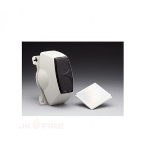
 Single Compact Housing Area coverage 50 metre or 100 metre model available 12-24 Vdc Operation Low current Consumption Robust Construction
 -
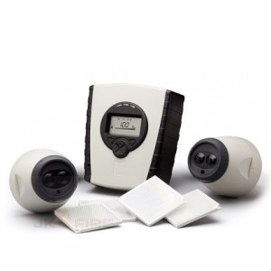
 Allows for 2 Detectors per System Controller Each Detector configurable from 8m to 100m Separate Fire and Fault relays per Detector Integral LASER alignment Auto-Align Fast Automatic Beam Alignment Building Movement and Contamination Compensation Low Level System Controller Logs the 50 most recent events per detector Programmable Sensitivity and Fire Thresholds 20mm Cable Gland Knockouts on System Controller 2-wire interface from System Controller to Detector
 -

-
 Allows for 2 Detectors per System Controller Each Detector configurable from 8m to 100m Separate Fire and Fault relays per Detector Integral LASER alignment Auto-Align Fast Automatic Beam Alignment Building Movement and Contamination Compensation Low Level System Controller Logs the 50 most recent events per detector Approved to EN54:12 and UL268
 -
 Single Compact Housing Area coverage 50 metre or 100 metre model available 12-24 Vdc Operation Low current Consumption Robust Construction
 -

-
 PCB mounts inside the CFP fire panel. Outputs are NOT designed to switch mains voltages.
 -
 PCB mounts inside the CFP fire panel. Outputs are NOT designed to switch mains voltages.
 -
 PCB mounts inside the CFP fire panel. Outputs are NOT designed to switch mains voltages.
 -
 Key Features:; Provides four panel-controlled volt free relay outputs (reset, fault, aux. fire and remote) and eight output per zone relays. PCB mounts inside the CFP fire panel. Reset relay is active during the panel’s reset cycle. Fault relay is active in any fault condition. This relay is failsafe and normally energised - if power is removed from the panel the relay will changeover to produce a fault signal. Aux. fire relay is active in an alarm condition provided all relevant delays have expired. Remote relay is active during any Alarm Condition provided all relevant delays have expired. Output per zone relays will changeover when the corresponding zone is in alarm (subject to certain conditions - for full details refer to the instructions, downloadable below). Outputs are NOT designed to switch mains voltages.
 -
 Key Features:; Provides four panel-controlled volt free relay outputs (reset, fault, aux. fire and remote). PCB mounts inside the CFP fire panel. Reset relay is active during the panel’s reset cycle. Fault relay is active in any fault condition. This relay is failsafe and normally energised - if power is removed from the panel the relay will changeover to produce a fault signal. Aux. fire relay is active in an alarm condition provided all relevant delays have expired. Remote relay is active during any Alarm Condition provided all relevant delays have expired. Outputs are NOT designed to switch mains voltages.
 -
 Key Features:; Allows the connection of up to eight CFP760 Repeaters (one CFP761 required per Main, all CFP760 repeaters include a CFP761 as standard) Communicates over screened two-wire fire resistant cable Total repeater network cable length should not exceed 1KM
 -
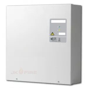
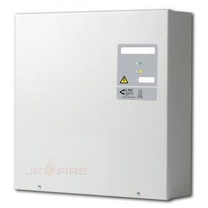
 C-Tec 24v 5A EN54-4/A2 Boxed Power Supply Unit (VDS Certified); BF362-5; Low current consumption Deep discharge battery protection and EN54 compliant reporting of battery impedance faults Single-pole volt-free changeover relay that switches for any fault condition Three LED indicators - supply present, general fault and auxiliary fault (for optional connection to third-party equipment) Link selectable battery charging capacity Environmentally-friendly charging circuit - dissipates just 0.35W compared to the industry norm of around 2.55W. Optional high-temperature output activates when internal box temperature reaches 55oC, for connection to ventilation fans, etc. Optional handheld status reader (shows internal temperature, charging voltage and current of connected PSU). Serial data link also provided for third-party OEM equipment All boxed versions third-party certified to EN54-4 (1997/A2:2006) by the VdS or LPCB
 -
 C-Tec 24v 3A EN54-4/A2 Boxed Power Supply Unit (LPCB Certified) BF362-3; Low current consumption Deep discharge battery protection and EN54 compliant reporting of battery impedance faults Single-pole volt-free changeover relay that switches for any fault condition Three LED indicators - supply present, general fault and auxiliary fault (for optional connection to third-party equipment) Link selectable battery charging capacity Environmentally-friendly charging circuit - dissipates just 0.35W compared to the industry norm of around 2.55W. Optional high-temperature output activates when internal box temperature reaches 55oC, for connection to ventilation fans, etc. Optional handheld status reader (shows internal temperature, charging voltage and current of connected PSU). Serial data link also provided for third-party OEM equipment All boxed versions third-party certified to EN54-4 (1997/A2:2006) by the VdS or LPCB
 -
 C-Tec 24v 1.5A EN54-4/A2 Boxed Power Supply Unit (VDS Certified); BF362-1; Low current consumption Deep discharge battery protection and EN54 compliant reporting of battery impedance faults Single-pole volt-free changeover relay that switches for any fault condition Three LED indicators - supply present, general fault and auxiliary fault (for optional connection to third-party equipment) Link selectable battery charging capacity Environmentally-friendly charging circuit - dissipates just 0.35W compared to the industry norm of around 2.55W. Optional high-temperature output activates when internal box temperature reaches 55oC, for connection to ventilation fans, etc. Optional handheld status reader (shows internal temperature, charging voltage and current of connected PSU). Serial data link also provided for third-party OEM equipment All boxed versions third-party certified to EN54-4 (1997/A2:2006) by the VdS or LPCB


