-
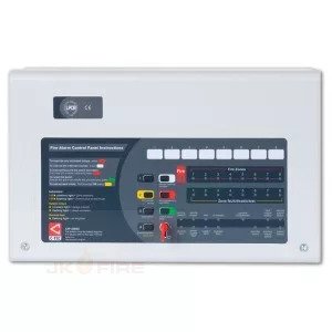
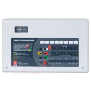
 "Third-party certified to EN54 parts 2 and 4 by the Loss Prevention Certification Board (LPCB) with optional EN54 part 13 compliance from the BSI. Intuitive user-friendly interface with colour-coded buttons and combined keypad/keyswitch entry. Manufactured by C-TEC in the UK. Two detector zone circuits. Four conventional sounder circuits Integral 1.5A EN54-4/A2 compliant switch mode PSU. Wide range of engineering functions including zone test, coincidence, zone delay and non-latching zones. Two on-board relays (Fire and Fault). Two open-collector outputs (Remote and Reset). 'Class change' and alert inputs. Installer-friendly design. Attractive flush or surface mountable plastic lid and enclosure - no bezel required. Low 25mA quiescent current. Multiple indicators. System expansion connections provided for up to eight two-wire repeaters (one CFP761 network card required per system), optional CFP relay boards and optional EN54-13 compliant sounder circuit boards. Space for two x 12V 3.3Ah VRLA batteries. Fully compatible with C-TEC's ActiV range of conventional fire detectors."
 -
 Key Features:; Up to 8 repeaters per CFP master Includes its own Mains power supply that requires its own standby battery supply Provides the user with access to all AL1 and AL2 functions Master/Repeater communication achieved using CFP761 network driver cards (one CFP761 is supplied with the Repeater, an additional CF761 card is required at the master CFP) Communicates over screened two-wire fire resistant cable Total repeater network cable length should not exceed 1KM Attractive flush or surface mountable plastic lid and enclosure - no bezel required
 -

-
 Key Features:; BSI certified to EN54-13 (Fire detection and fire alarm systems, compatibility assessment of system components). Detects resistances down to 10 ohms. One required per BF354 interface board sounder circuit Measures 50mm x 26mm x 5mm with 100mm tail (can be be fitted inside or alongside the last device on the sounder circuit).
 -
 PCB mounts inside the CFP fire panel. Outputs are NOT designed to switch mains voltages.
 -
 PCB mounts inside the CFP fire panel. Outputs are NOT designed to switch mains voltages.
 -
 PCB mounts inside the CFP fire panel. Outputs are NOT designed to switch mains voltages.
 -
 Key Features:; Provides four panel-controlled volt free relay outputs (reset, fault, aux. fire and remote) and eight output per zone relays. PCB mounts inside the CFP fire panel. Reset relay is active during the panel’s reset cycle. Fault relay is active in any fault condition. This relay is failsafe and normally energised - if power is removed from the panel the relay will changeover to produce a fault signal. Aux. fire relay is active in an alarm condition provided all relevant delays have expired. Remote relay is active during any Alarm Condition provided all relevant delays have expired. Output per zone relays will changeover when the corresponding zone is in alarm (subject to certain conditions - for full details refer to the instructions, downloadable below). Outputs are NOT designed to switch mains voltages.
 -
 Key Features:; Provides four panel-controlled volt free relay outputs (reset, fault, aux. fire and remote). PCB mounts inside the CFP fire panel. Reset relay is active during the panel’s reset cycle. Fault relay is active in any fault condition. This relay is failsafe and normally energised - if power is removed from the panel the relay will changeover to produce a fault signal. Aux. fire relay is active in an alarm condition provided all relevant delays have expired. Remote relay is active during any Alarm Condition provided all relevant delays have expired. Outputs are NOT designed to switch mains voltages.
 -

-

-


