-
 Zones 0, 1, 2, 20, 21 and 22 ATEX and IECEx approved IP66 rated Surface Mount Polycarbonate housing material; C-Tec - Electronic Sounder - Datasheet C-Tec - Installation Guide
 -
Approved by ATEX, IECEx Group I MI Ex ia I Ma f Group II IGD Ex ia IIC T6 Ga Ex ia IIIC T850 C Da Zones 0, 1, 2, 20, 21 & 22 Conforms to: EN 60079-0:2012 + All:2013 (IEC 60079-0:2011) EN-60079-11:2012 + (IEC 60079-11:2011) Diode Polarised & End of line resistor compatible White base version available MOQ apply Dustproof & Weatherproof; C-Tec - LED Beacon - Datasheet C-Tec - Installation Guide
-
Approved by ATEX, IECEx Group I MI Ex ia I Ma f Group II IGD Ex ia IIC T6 Ga Ex ia IIIC T850 C Da Zones 0, 1, 2, 20, 21 & 22 Conforms to: EN 60079-0:2012 + All:2013 (IEC 60079-0:2011) EN-60079-11:2012 + (IEC 60079-11:2011) Diode Polarised & End of line resistor compatible White base version available MOQ apply Dustproof & Weatherproof; C-Tec - LED Beacon - Datasheet C-Tec - Technical Information C-Tec - Installation Guide
-
Approved by ATEX, IECEx Group I MI Ex ia I Ma Group II IGD Ex ia IIC T6 Ga Ex ia IIIC T850 C Da Zones 0, 1, 2, 20, 21 & 22 Conforms to: EN 60079-0:2012 + All:2013 (IEC 60079-0:2011) EN-60079-11:2012 + (IEC 60079-11:2011) Diode Polarised & End of line resistor compatible White base version available MOQ apply Dustproof & Weatherproof; C-Tec - LED Beacon - Datasheet C-Tec - Technical Information C-Tec - Installation Guide
-
Approved by ATEX, IECEx Group I MI Ex ia I Ma Group II IGD Ex ia IIC T6 Ga Ex ia IIIC T850 C Da Zones 0, 1, 2, 20, 21 & 22 Conforms to: EN 60079-0:2012 + All:2013 (IEC 60079-0:2011) EN-60079-11:2012 + (IEC 60079-11:2011) Diode Polarised & End of line resistor compatible White base version available MOQ apply Dustproof & Weatherproof; C-Tec - LED Beacon - Datasheet
-
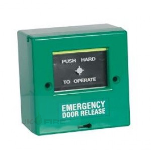
Certified to EN54 Part 11 (LPCB/VdS). Unique ‘Plug & Play’ installation concept. Supplied with a non-breaking plastic resettable element. Includes a 470? resistor, test key and red back box. Anti-Tamper facility. Flush version (without a red back box) also available (order code BF370MFR).; Technical Specification; Approvals/certifications - Certified to EN54 Part 11 by the LPCB & VdS. Supply/operating voltage - 30Vdc max. Product dimensions (mm) - 93 W x 89 H x D 60mm (includes back box). 28mm D without back box. Construction & finish - Red ABS. Plastic element. IP Rating - IP24D. Weight -180g (130g without back box). Properties - Supplied with a 470? resistor. Operating conditions/temperature - -10ºC to +55ºC.
-
-
-
-
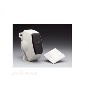
Single Compact Housing Area coverage 50 metre or 100 metre model available 12-24 Vdc Operation Low current Consumption Robust Construction
-
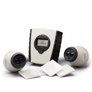
Allows for 2 Detectors per System Controller Each Detector configurable from 8m to 100m Separate Fire and Fault relays per Detector Integral LASER alignment Auto-Align Fast Automatic Beam Alignment Building Movement and Contamination Compensation Low Level System Controller Logs the 50 most recent events per detector Programmable Sensitivity and Fire Thresholds 20mm Cable Gland Knockouts on System Controller 2-wire interface from System Controller to Detector
-
-
-
-
Allows for 2 Detectors per System Controller Each Detector configurable from 8m to 100m Separate Fire and Fault relays per Detector Integral LASER alignment Auto-Align Fast Automatic Beam Alignment Building Movement and Contamination Compensation Low Level System Controller Logs the 50 most recent events per detector Approved to EN54:12 and UL268
-
-
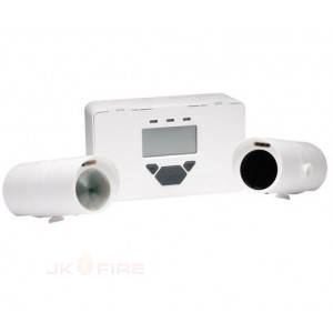
Key Features:; Allows for 2 Detectors per System Controller Range 5 to 120 metres, configurable per set of Detectors Integral Laser Alignment in Receiver 2-wire Interface between Controller and Receiver Separate Fire and Fault Relays per Detector Low Level Controller with LCD display Programmable Sensitivity and Fire/Fault delay Automatic Gain Control (AGC) for drift compensation First Fix concept for Transmitter, Receiver and Controller Multiple cable gland knockouts for ease of wiring Transmitter can be powered from Controller
-
Single Compact Housing Area coverage 50 metre or 100 metre model available 12-24 Vdc Operation Low current Consumption Robust Construction
-
-
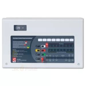
"Third-party certified to EN54 parts 2 and 4 by the Loss Prevention Certification Board (LPCB) Intuitive user-friendly interface with colour-coded buttons and combined keypad/keyswitch entry Manufactured by C-TEC in the UK Eight detector zone circuits Four conventional sounder circuits Integral 1.5A EN54-4/A2 compliant switch mode PSU Wide range of test and fault-finding facilities Four open-collector outputs (Fire, Fault, Remote and Reset) 'Class change' and alert inputs Installer-friendly design Attractive flush or surface mountable plastic lid and enclosure - no bezel required Low 25mA quiescent current Multiple indicators No system expansion connections Fully compatible with C-TEC's ActiV range of conventional fire detectors"
-
"Third-party certified to EN54 parts 2 and 4 by the Loss Prevention Certification Board (LPCB) Intuitive user-friendly interface with colour-coded buttons and combined keypad/keyswitch entry Manufactured by C-TEC in the UK Two detector zone circuits Four conventional sounder circuits Integral 1.5A EN54-4/A2 compliant switch mode PSU Wide range of test and fault-finding facilities Four open-collector outputs (Fire, Fault, Remote and Reset) 'Class change' and alert inputs Installer-friendly design Attractive flush or surface mountable plastic lid and enclosure - no bezel required Low 25mA quiescent current Multiple indicators No system expansion connections Fully compatible with C-TEC's ActiV range of conventional fire detectors"
-
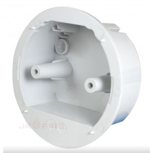
Key Features; A bespoke alternative to standard metal conduit boxes. Simplifies the installation of C-TEC manufactured fire detector bases and base sounder/VADs on ceiling tiles, solid ceilings, wooden beams, etc. Can be mounted directly onto a surface or in recesses behind ceiling tiles and plasterboard. Multiple access wiring points and lots of working space. Features two anti-rotation spikes. Easy termination of 16mm or 20mm cable glands ivia side and rear drill-out cable entry points.
-
-
-
-
Key Features:; Provides four panel-controlled volt free relay outputs (reset, fault, aux. fire and remote). PCB mounts inside the CFP fire panel. Reset relay is active during the panel’s reset cycle. Fault relay is active in any fault condition. This relay is failsafe and normally energised - if power is removed from the panel the relay will changeover to produce a fault signal. Aux. fire relay is active in an alarm condition provided all relevant delays have expired. Remote relay is active during any Alarm Condition provided all relevant delays have expired. Outputs are NOT designed to switch mains voltages.
-
Key Features:; Provides four panel-controlled volt free relay outputs (reset, fault, aux. fire and remote) and eight output per zone relays. PCB mounts inside the CFP fire panel. Reset relay is active during the panel’s reset cycle. Fault relay is active in any fault condition. This relay is failsafe and normally energised - if power is removed from the panel the relay will changeover to produce a fault signal. Aux. fire relay is active in an alarm condition provided all relevant delays have expired. Remote relay is active during any Alarm Condition provided all relevant delays have expired. Output per zone relays will changeover when the corresponding zone is in alarm (subject to certain conditions - for full details refer to the instructions, downloadable below). Outputs are NOT designed to switch mains voltages.
-
PCB mounts inside the CFP fire panel. Outputs are NOT designed to switch mains voltages.
-
PCB mounts inside the CFP fire panel. Outputs are NOT designed to switch mains voltages.
-
PCB mounts inside the CFP fire panel. Outputs are NOT designed to switch mains voltages.